Many facilities require cooling during the cold winter months. Northern climates such as Michigan or Ohio may not have any latent load in the cold winter months. The load may be only sensible from people and equipment. What happens if a coil system designed for a 45°F or 42°F supply receives a higher temperature from the chiller or a water side economizer? How is the output of the coil affected?
Warmer Chilled Water Supply from Water Side Economizers
In the R. L. Deppmann Monday Morning Minutes Water Side Economizers Part 2: State Energy Codes we blogged about the ASHRAE 90.1 energy standard requirement for water side economizers or free cooling heat exchangers when the outdoor air temperature dropped to 45°F wet bulb. The chilled water supply temperature from a heat exchanger, at those temperatures, can be much higher than the design, as discussed in our blog Water Side Economizers Part 4: Chilled Water Temperatures.
Whether the warmer supply water is a result of chiller reset or water side economizers, what happens at the coil? Let’s journey into the world of heat transfer and see what happens when the flow rate drops and the chilled water supply temperature rises.
Basic Heat Transfer Formula
The chilled water coil is transferring heat from the warm air to the hydronic system water pumped from the chilled water system. The coil is selected by programs based on the simple heat transfer formula:
BTUH=U x A x LMTD
Where BTUH is the chilled water load, “U” is the heat transfer coefficient, LMTD is the log mean temperature difference between the air side and the water side, and “A” is the unknown or area of the coil which we are sizing.
What if the winter load is only 25% of the design load and only requires sensible cooling? The area of the coil did not change so the two variables are “U” and “LMTD”.
Dropping Flow Rate and the “U” Value
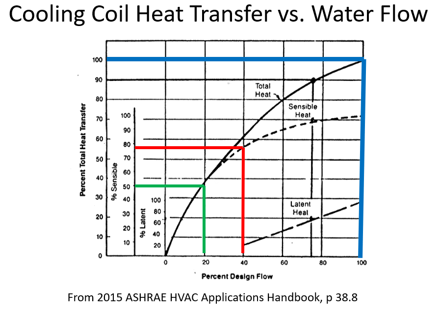
It’s difficult to show a great deal of numbers without running coil sizing programs in the performance mode given a specific coil. We can look at ASHRAE and Bell & Gossett handbooks for a chart we use often for hydronic flow balance discussions.
This chart tells us that at 100% flow rate, the blue lines, the coil will produce 100% of the design BTUH. Good, we sized it correctly. At 40% of the design flow rate, we will get 75% of the sensible capacity. At 20% flow rate, we will get 50% of the sensible capacity. The chart is based on a standard, old-school, temperature range of 45°F to 55°F. As the load drops, the two-way valve throttles and the flow is reduced. The flow is affecting the “U” valve to reduce the output.
Another chart tells us that the water temperature rise will almost double when the flow rate drops to 20%. This will affect LMTD but only about a 10% drop. The flow is the bigger part of the drop in capacity.
Please note that this chart is based on water and not glycol. Glycol will have different turbulent flow limits which would change the numbers and result.
Raising the Supply Temperature and the LMTD Value
We know if we drop the flow rate, the BTUH will drop. The drop in BTUH output to match the winter load is primarily due to the dropping “U” value. What happens when we raise the chilled water supply temperature?
The LMTD or log mean temperature difference is the formula to determine how close the hot side fluid or air and the cold side fluid or water are to each other. Visit any one of the many internet site calculators or logarithmic mean temperature difference.
When the chilled water supply temperature jumps from 45°F to 55°F, the chilled water delta T will rise. The warmer average water temperatures will make the ”U” value rise but it will be insignificant. The real change will occur in both the LMTD and, possibly, the outlet air temperature.
The change in the supply temperature shown above will drop the LMTD by 35 – 50% depending on the coil design and the air temperatures. If the coil cannot keep up with the lower LMTD and the lower “U” value, the two-way valve will open. This will allow more flow rate to raise the “U” value and the BTUH output.
The Results
Raising the supply temperature will result in the main system pump increasing speed and flow rate.
You can expect the system pump to be operating at a higher speed when the water side economizer is operational, and the heat exchanger chilled water supply temperature is warmer than the design supply temperature. This will use more pump horsepower but less or no chiller compressor horsepower. In the world of energy savings, less chiller HP will always trump less pump HP.
Well, hope I did not bore you, but this question did come up in a recent seminar. It is important for the engineer to understand what to expect when warmer chilled water supply temperatures exist. Next week I’ll talk about equipment a bit with the warmer subject of boilers.


