Printer Friendly (PDF)
 An engineer in the Detroit area asked a question we get asked every month of every year. The way he asked it caught my attention. His client had a couple of old steam boilers and they were producing steam which was converted to hydronic heating hot water through a Bell & Gossett series SU heat exchanger. The client was concerned because the “old” heat exchanger was installed in 1946 and maybe it was approaching the end of its life. While they were doing the study they might as well look at the “new” one which was installed in 1966. We hear these stories regularly when it comes to B&G equipment. Oftentimes we are consulted by the engineer to assist in determining the BTUH capacity of an existing Bell & Gossett SU heat exchanger. There are tricks we can use to back into the load.
Bell & Gossett Series SU Steam to Water (Liquid) Converters
There I go introducing a new word: converter. The SU heat exchangers were also called converters because they converted steam heat to water heat. These heat exchangers are still in existence today and still provide great results for new installations. They are available today in single or double wall but look very similar to the 1946 variety mentioned above. Let’s start with a little engineering.
When calculating any coil or heat exchanger area required, we use the formula:
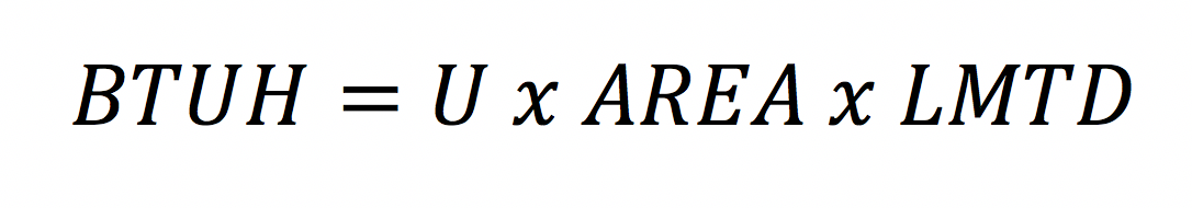
Where the U value is dependent on the velocity, temperature, and materials of construction; LMTD is the log mean temperature difference between the steam temperature and the liquid temperature. The heat exchanger is existing so the area is known. If we can estimate the LMTD and U valve of an existing Bell & Gossett SU converter, we can get reasonably close to the BTUH load. Before we go there, let’s get some field information.
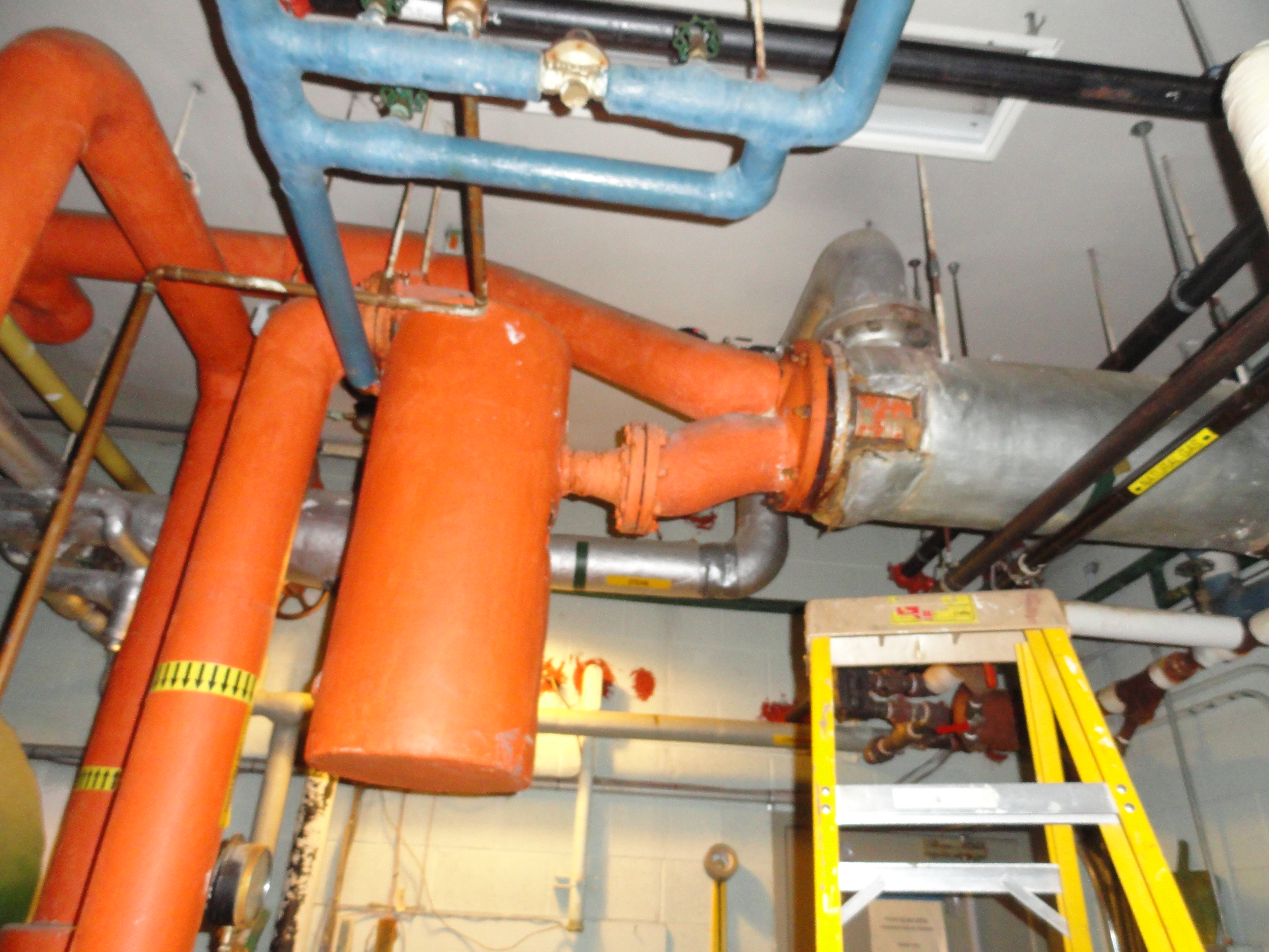
A Picture is Worth 1000 Words: Your Field Study Data
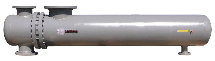
The first step is to identify what is out there in the mechanical equipment room. The photo above is a Bell & Gossett SU heat exchanger. Notice the ASME tag which contains the model number and serial number. It is located at the right side of the heat exchanger when starting at the tube side head. It is normally between 2 and 3 o’clock and just under the steam inlet nozzle or just to the right of the nozzle. It contains the model number, serial number, and date of manufacture. Because these heat exchangers are often insulated, you can count on the label being in the same location every time.
Now, look at the head. These exchangers normally had the liquid in the tubes and steam in the shell. What type of head is it? The size and orientation of the nozzles help us identify if it is 2-pass, 4-pass, or 6-pass and the size. There is also a casting number on the head.
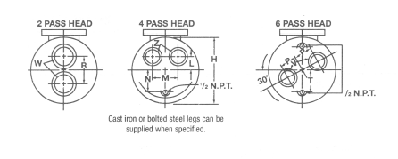
You can see from the clip above that the photo is a 4-pass heat exchanger. The casting number will give us the shell diameter which can also be obtained with a ruler.
Sometimes, the head may looked bumped out rather than flat. These are called flanged bonnet or channel heads. These are less common in heating system but often found in process systems.
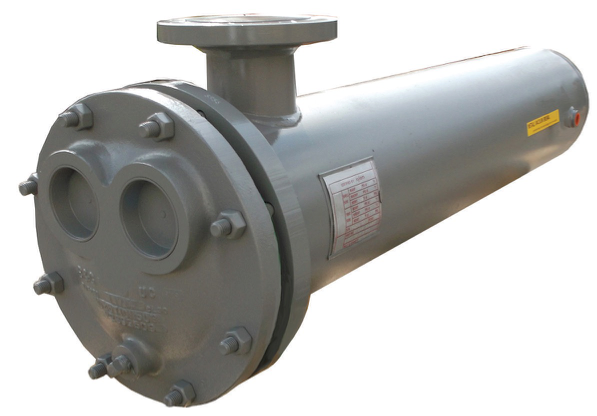
Finally, the length of the exchanger from the tube-sheet to the end will give the length. This is the “A” dimension in the image below minus the head dimension. If you give us the “A” dimension and a photo of the head, we can do the math.
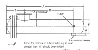
For our example, we will assume that the exchanger has a 10” diameter shell which is 5 feet long and is configured for 4-pass. Without any information to help us think otherwise, we assume we have a model SU-105-4. There may be something special but without the serial number it will be hard to know. Even if you found the nameplate and model you should read on for field information we will ask about to determine the capacity.
More Information You Need If You Are Replacing the Tube Bundle
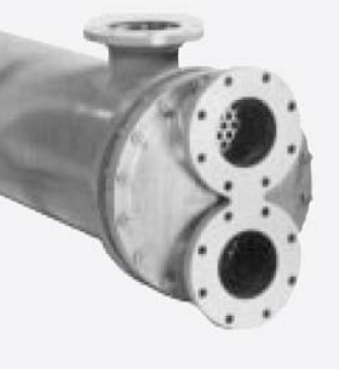
If you are replacing the tube bundle we will need to know whether the tube-sheet is full or a wafer style. The photos above show the “new” style bundle. The shell flange, head flange, and bundle tube-sheet look like an Oreo cookie with some of the filling gone. You can see the bolts in between.
The old style heat exchanger will have a bundle tube sheet that is the same diameter as the shell and head flange so you cannot see the bolts in the middle. Again, a picture will help when you contact us.
We also offer replacement tube bundles for anyone’s heat exchangers with a very fast lead time when needed. Call our customer service team at 800-589-6120.
Finally, You Can Take a Look at the System
One of the biggest tell signs is the relief valve capacity. If the tag is still on the water side relief valve, take a photo. Most state codes have required an ASME pressure relief valve between the exchanger and the shutoff valves for a long time.
What pipe size is the steam main going to the exchanger? What pipe size is the condensate return pipe? What size are the water supply and return pipes? By the way, is it water or glycol and, if glycol, what percentage? If you want to review some piping of the steam to water heat exchangers, try our blog from 2017 called Steam Inlet Pipe Size of Steam-to-Water Heat Exchangers.
Finally, what is the steam pressure at the heat exchanger inlet or control valve inlet? This will become important when attempting to determine the BTUH capacity which is Part 2 of this short series.