Printer Friendly (PDF)
 As I noted in our last R. L. Deppmann Monday Morning Minutes (Part 1), an engineer in the Detroit area asked a question we get asked every month of every year. But the way he asked it caught my attention. His client had a couple of old steam boilers that were producing steam which was converted to hydronic heating hot water using a B&G series SU heat exchanger. The client was concerned because the “old” heat exchanger was installed in 1946 and might be approaching the end of its life. While they were doing the study, they included a look at the “new” one which was installed in 1966. We hear these stories regularly when it comes to B&G equipment. Oftentimes we are consulted by the engineer to assist in determining the BTUH capacity of an existing B&G SU heat exchanger. There are tricks we can use to back into the load.
The last R. L. Deppmann Monday Morning Minutes explored methods to determine which heat exchanger model is installed in the existing system. How can we estimate the capacities?
We are going to use some rules of thumb from the 1970s and 1980s. Any engineer might use their own limitations, but in general the following are some guidelines.
Let’s Start by Talking About Velocity
In today’s world, heat exchangers are selected by computer. Many engineers will accept the first selection on the list that indicates the lowest price or size while meeting the capacity requirements. There are velocity limits on both the tube side and shell side of a steam to liquid heat exchanger and those are taken into account as part of the computer selection.
Back in the 1970s and 1980s, many of the selections were done by hand using paper catalogs. Those catalogs showed when you were getting close to the maximum recommended velocity. Engineers and the B&G representatives often moved to a larger size heat exchanger to avoid getting too close to this maximum velocity. Remember that balancing was not the science it is today. In addition, many three-way valves were installed with unbalanced bypasses which would cause flow rates to increase when in a part-load condition. To be safe, many engineers just wanted some “wiggle room” in the selection.
All of these reasons led us to select heat exchangers at less than the B&G maximum recommended velocity. The normal selection range back then was 4 to 5.5 feet per second (FPS) for the tube-side velocity.
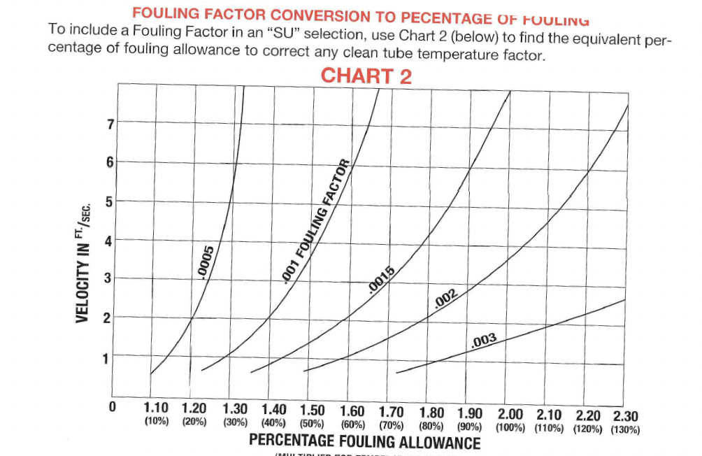
What About the Fouling Factor?
Fouling factors (FF) are added to the coefficient of heat transfer in shell and tube heat exchangers. This is a percentage of extra surface added to overcome the “film” that deposits on the copper tubes over time. This additional layer of thickness on the tubes creates additional resistance to heat transfer. The typical coefficients added are either 0.0005 or 0.001 fouling factors. Today, we tend to standardize on 0.0005 for closed hydronic systems. Back in the 1970s and 1980s we were more likely to see .001 FF added than the lighter 0.0005 FF.
What Steam Pressure Do You Have?
When looking at an existing heat exchanger, we must determine the design steam pressure in the shell of the B&G heat exchanger. The rule of thumb was to take 50% of whatever steam pressure you have in the mains before the control valve. If the steam pressure is 10 PSIG, then the heat exchanger would be sized on 5 PSIG. If the pressure in the main was 5 PSIG, the heat exchanger would be sized for 2 PSIG.
Temperature Estimation
You may be able to find information about the design temperature and the delta T on the project. You may be able to determine the set pressure of the temperature control valve. If not, let’s estimate. Today, heating systems would likely be a maximum of 180°F supply with a 30 or 40°F ∆T. Back in the 1960s and 1970s the world of hydronics used a 20°F ∆T and could have had a 200°F supply.
Computers vs. Catalogs for Estimating BTUH Capacity
Given the three assumptions above and the flow estimation from the pump data, it is time to estimate BTUH. Today, we use computers to select heat exchangers. These programs, such as the B&G ESP-Thermal, are available and have the capability to work backwards to determine the maximum capacity of an existing heat exchanger. The advantage of the catalog is that you can see the limitations and select to avoid the limits. Here is an example.
In the last R. L. Deppmann Monday Morning Minutes we mentioned a B&G SU-105-4 heat exchanger. Let’s assume we have 5 PSIG steam in the main and the fluid is 40% glycol and the connected pipe is 2-1/2”. What might we estimate is the capacity of this unit?
Old School Catalog Methods
The old B&G SU catalogs used what they called “tube factors” to determine the size of a heat exchanger. There was a clean tube factor based on the steam pressure and water temperature. This factor was multiplied by a percentage from the fouling allowance and also for the fluid type. Look at the clip below.
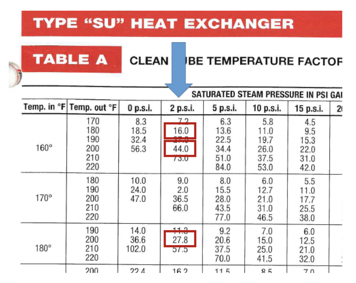
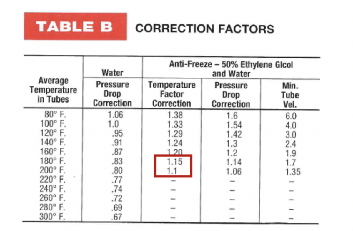
The clean tube factor is boxed for 2 PSIG steam (50% of the 5 PSIG main). Depending on the design temperatures, the factor changes. Next we look at corrections to this number. Let’s start with an assumption of a 0.0005 fouling factor. We also know there is glycol in the system so we correct for that too. These are all estimates.

Finally, we look at the tube factors for that Bell & Gossett SU-105-4 and use our best Sherlock Holmes imitation.
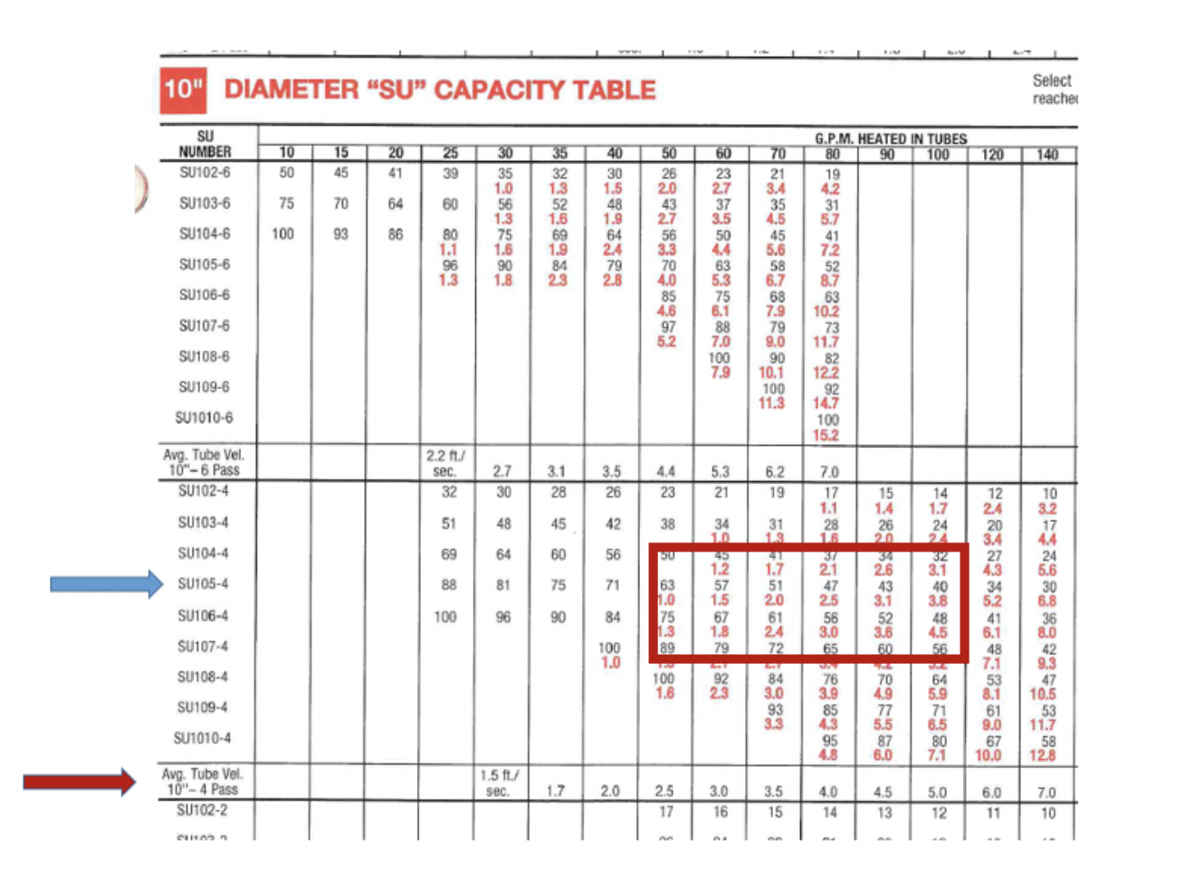
If the factor required was 23, we would have velocities near the maximum. This would be unlikely as a selection. I would eliminate the 160 to 180 temperature range. If the factor was 38.92, it fits nice in the 5 FPS velocity range at 100 GPM. In addition, if the fouling factor was indeed 0.001 at design, the factor would be about 48 and this unit fits at 70 GPM.
If the factor required was 63.25, this unit would be selected at a very low velocity of about 2.5 FPS and 50 GPM. There would be a good chance that a smaller diameter, less expensive model could have been used. The only reason to use this larger unit would be if the space required to pull the tube bundle was real tight. This is something you can tell on the job site.
The 2-1/2” pipe also contributes to our knowledge. At 100 GPM the friction loss would be 7 ft./100. At 50 GPM it would be less than 2 ft./100. At 70 GPM it is just right at 3.5 ft./100. So based on the information this unit might either be 50 GPM from 160 to 200 or 70 GPM from 160 to 180.
The pump information may shed some light. The space available may shed some light. If the room for tube pull is not tight, then I would make the call for the 70 GPM unit. The 20°F ∆T is compelling. The fact that we could have done the 50 GPM in a smaller unit is also compelling.
I would assume this unit to be around 700,000 BTUH. Sherlock has spoken!
Call Your B&G Representative
We do a little of the system design day after day. Heat exchangers are something we know well. You have many more things to know and do, so just give us a call and let us help you find the solution.
If you are in Northern Ohio or Michigan, contact our customer service department for help with these challenges. If you are in another area, call your B&G representative.