There are some engineers who challenge the use of balancing valves at all in hydronic systems. If the control valve throttles the flow to satisfy room conditions, why not depend on that to determine the proper flow? There are three very good reasons to use balance and flow measuring devices in addition to the control valves. This week the R. L. Deppmann Monday Morning Minutes continues to look at balancing and flow measurement in hydronic systems.
Let’s use an example to explain the three reasons.
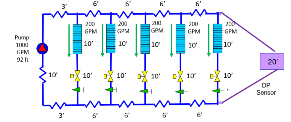
Here is a simple system with 6 zones. To make things easier to see, I made the design flow rates all the same. Each zone could be several terminal units, a single air handling unit, or an entire floor of a larger building. Long before the balancing contractor arrives to throttle the balance valves, Mother Nature will use physics to balance this system. What does this system look like before it is balanced? Let’s use an example system to see what this looks like.
Six Good Reasons to Use Balance and Flow Measurement Valves
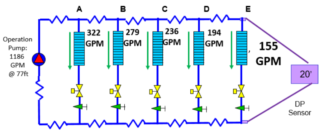
Mother Nature has balanced the system but she does not match what the engineer has requested on the drawings. Taking a look at the sketch above, let’s dissect what the numbers tell us.
Reason #1 – Velocity: The flow rate in zone “A” is over 50% higher than design. That means the velocity could be causing some damage. One could argue that this would only occur at the initial startup, but that may not be the whole story. It will occur after the night setback. It will occur when diversity exists.
Reason #2 – Time to cool or heat: When the system set-point is changed after a night setback, Zone”A” control valve will be wide open until the room temperature is close to satisfied. ASHRAE tells us that over pumping a terminal unit by “X” does not reward us with the same percentage of heat transfer. While the zone “A” is cooling, Zone “E” does not have enough flow rate. How long will it take for zone“A” to be satisfied? Once zone “A” is under control, zone “B” has to also get satisfied and that takes time. Meanwhile, the people in zone “E” may be complaining.
Reason #3 – Energy waste: As mentioned above, when we are over pumping a zone, the benefit is very limited.
Reason #4 – Reduced stroke: The example system above would require 48 feet of throttle during design for zone “A” . If you think that sounds like a lot, think again. Have you ever designed a direct return secondary pumping system with about 100 feet of head? What does the first terminal unit near the mechanical room need to achieve design flow? All the rest of that 100 foot head pump must be throttled across the balance valve.
If zone “A” above does not have a balance valve, the control valve must throttle 48 feet before it even begins to throttle for temperature control. At that point the control valve may be acting more like a two-way on-off valve rather than a modulating valve. If the pump head is too great, the control valve may even begin to cavitate. We will address this more in the next blog.
Reason #5 – Pump damage: This is a simple little system but the pump is flowing 10% more flow than design and this example assumes you put very little safety factor in the pump head calculation. Depending how close to the end of curve you selected the pump, this operation point may be off the end of curve and at that point you may damage the pump. The more safety, the more potential damage. The more diversity, the more potential damage.
Reason #6 – Lack of a forensics tool: We often think of balance and flow measurement valves as a commissioning tool. That flow measuring portion of the valve can become invaluable when troubleshooting systems down the road. If the control valve is used for the balance, we lose this valuable asset.
Stay tuned for Part 3 of our MMM Series on balance valves and variable speed pumping in HVAC hydronic systems.
Discover more on this Series: Balancing HVAC Hydronic Systems:
Balancing HVAC Hydronic Systems: Flow Tolerance (Part 1)
Balancing HVAC Hydronic Systems: Flow Measurement Valves (Part 3)
Balancing HVAC Hydronic Systems: Automatic Flow Limiting (Part 4)
Balancing HVAC Hydronic Systems: Pressure Independent Control Valve (Part 5)


