Printer Friendly (PDF)
 The HVAC engineer or designer has many choices when it comes to the control of variable speed pumps. The traditional differential pressure (DP) transmitter near the farthest or controlling zone is traditional in direct return systems. This is one method that I refer to as “Area Control.” The new kid on the block in pump control is variable frequency drives with integrated quadratic pump control logic. This is sometimes called sensorless control. I refer to this type of control as “curve control.” Let’s explore “curve control” a little more.
HVAC Variable Speed Pumping Control Curves
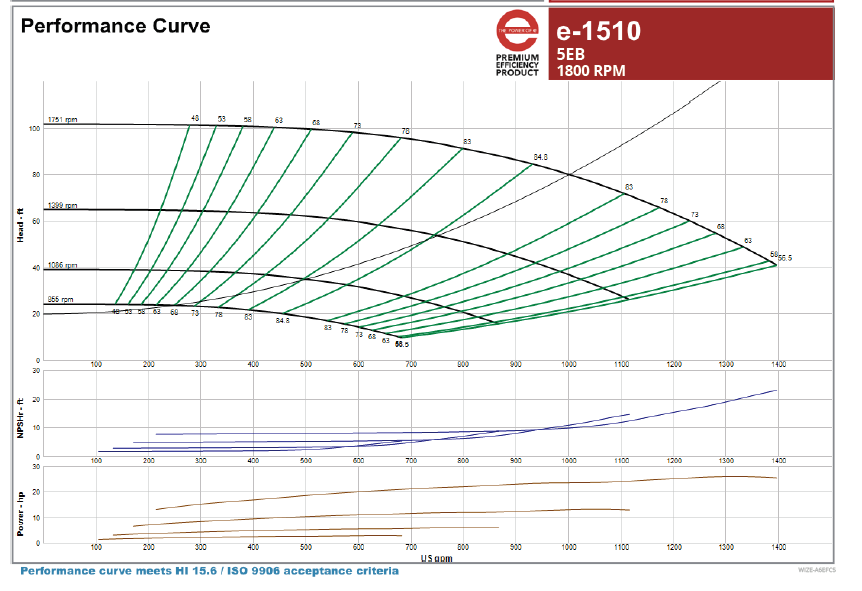
When engineers and pump manufacturers show a variable speed pump curve, we also like to show a control curve. The control curve is simply a system curve elevated by the expected “control head” or differential pressure (DP) setting. In a previous R. L Deppmann Monday Morning Minutes, I showed the change of control head depending on where the DP sensor is located. Here is the pump curve from that article with the control curve highlighted.
In the last Monday Morning Minute, I blogged about HVAC Variable Speed Pump Control Diversity. When there is a fair amount of diversity, the required flow and head points will vary significantly from the control curve. If the load in a hydronic system rises and drops uniformly in all zones, the required pump head is very close to the control curve.
Bell & Gossett provides pump controllers with Integrated Technologic Sensorless Controls. These controllers sense the KW being used by the motor and adjust the speed of the pump so it rides on the control curve. Let’s look at some numbers for the curve above.
The design is 1000 GPM at 80 feet. The control head is 20 feet and is a constant regardless of where the control valves are operating. That makes the variable head loss in this system 60 feet (total pump head minus control head). The pump affinity laws say that if I have half of the flow rate, I need 1/4 of the pump head. At 500 GPM, the variable pump head is 1/4 of 60 (15 feet). The total pump head will be the variable pump head plus the constant control head or 15 plus 20 is 35 feet. You can see that 500 GPM at 35 feet is on the control curve shown above.
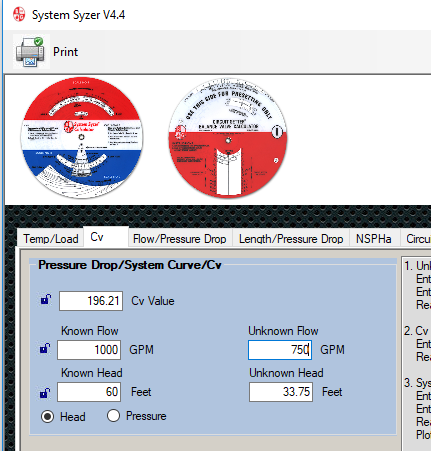
If every two-way valve is throttling flow to exactly 50% at the same time, we will follow the system curve. At 75% flow rate in every zone, the flow rate will be 750 GPM. We can use the B&G System Syzer to calculate the variable head as 33.75 feet, so the total pump head required is 53.75 feet which is on the system curve.
It is clear from this example that we could use a formula built into the pump controller and we would not need a differential pressure sensor in the system. We need to enter the expected pump control head or minimum head, the pump curve formula, and the KW to speed formula. You may recognize that the building management system could do this but they would spend thousands of dollars in programming time to even get close to all of this curve fitting requirement. This also assumes they completely understand the hydraulics of systems and can calculate the tiny changes in KW along the system curve. By the time you pay for that, you would have been further ahead putting the DP transmitter in knowing it would work.
The Bell & Gossett ITSC Pump Controller is Perfect for Low Diversity Systems.
B&G knows their curves and the KW required at various speeds. In addition, they can spend the programming dollars mentioned above and spread the cost over thousands of pump installations. The prudent use of your client’s capital dollars is to specify the B&G pump of your choice and couple it with a B&G Technologic ITSC pump controller.
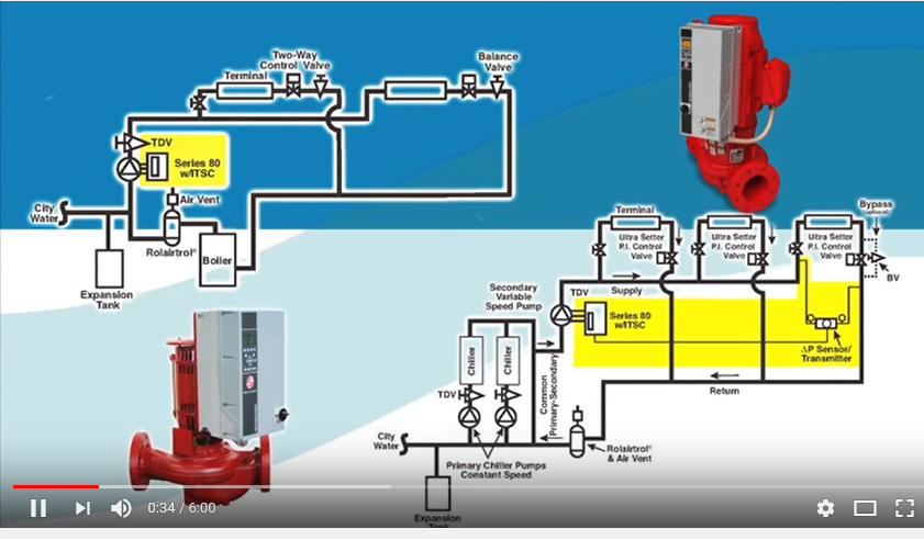
Here is a video explaining the operation of the sensorless controller. The video says it is only available on inline pumps, but since the video was produced, B&G has made it available for all types of our pumps including base mounted pumps. You can choose the B&G pump you want and then choose the pump control you want as two separate decisions.
Give your B&G representative’s sales engineer an email, text, or call for more information on using this product for your application. You may also fill out the inquiry card and we’ll have someone contact you quickly.
Next week, in the R. L. Deppmann Monday Morning Minutes we will interrupt the variable speed control series to solve a problem I call, “Unhide the makeup water in your hydronic system design”. The following week we return to our high school variable speed pumping example where there is clearly diversity in the system.
Discover more on this Series:
HVAC Variable Speed Pump Curve Control: Part 1
Variable Speed Pump Area Control & System Diversity: Part 3
Variable Speed Pump Control & Automatic Balance Valves : Part 4