Printer Friendly (PDF)
 Let me start by wishing everyone a Happy and Prosperous New Year. This blog begins the 14th year of the R. L. Deppmann Monday Morning Minutes. Look forward to a new indexing system of these articles to be announced later this quarter. Now to the subject of the blog.
Pumping from an open storage tank into a system or another tank is simple. A question comes up frequently about controls. Besides the pump, tank, and pipe trim, what protections and control devices should I consider? This is answered today in part 3 of the three-part series “Pumping from an Atmospheric Tank.”
Part one of this series spoke to the Pump Selection and Installation. Part two, Pump and Tank Piping focused on assisting the engineer or contractor with piping and tank openings on the pump suction. This blog will identify the needed tank controls and pump controls you may wish to employ.
This article addresses a tank and pump which is feeding another system and that system determines whether the pump operation is needed or not. There are also tanks that are pumped down and the control is within the tank. This is like a condensate pumping unit that stores water and pumps the tank level down when the tank is full. We are not addressing controls for a pump down application in this blog.
Tank Controls for Most Operations
The open or atmospheric storage tank can be an engineered reservoir or as simple as a 55-gallon drum. The controls mentioned here assume automatic operation of the system. If the system is operated manually with someone watching the tank, some controls may be eliminated.
Basic Tank Controls: Low Water Cutoff
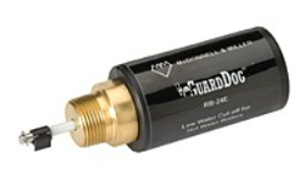
- The first control I recommend is a low-level pump cutoff switch. Part two of the series described the minimum recommended liquid level above the pump. If the system is calling for pump operation but the level is too low or the tank is empty, how do we protect the pump from damage. A low water cutoff switch. The switch is wired in series with the on-off or enable-disable contacts that start the pump. It could be electronic such as the Xylem McDonnell & Miller RB-24E low water cutoff shown above.
- It could also be a float type available from many suppliers including McDonnell & Miller. Keep the float away from the water supply coming into the tank.
Basic Tank Controls: Tank Fill Controls
- The tank may be filled manually or automatically. When filling automatically you need a float or electronic sensing to turn the source of water on and something at a different level to turn the source off. Make sure the water fill connection is not on the same side of the tank as the outlet. This will assist in keeping the flow of water out to the pump smooth and air free.
- Obviously, the level between the on-off should be adequate for the system requirements you are pumping into. Another concern is the number of starts per hour of the pump. The level in the tank may play into that. More about starts later in the blog.
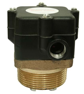
- You may also want a high-water alarm in case the fill valve is misfunctioning. The McDonnell & Miller RS sensors shown above is an example of a probe style that uses conductance of the water. A sensor system with probes could manage the on-off of the supply as well as the low water cutoff and high-water alarm if the water can conduct properly.
Pump Control: Constant Speed
- The pump will be started from whatever system requirements demand the water be provided. If the pump is constant speed and, on a starter, or contractor, it would be advantageous to make sure the pump does not start and stop more than six times per hour. We do not want the pump turning on and off with a standard motor. There could be damage to the motor, or we could arc the contacts on the starter.
- The other concern is minimum flow. If the system will operate at various flow rate needs, make sure the minimum possible flow rate is above the minimum flow recommended by the pump manufacturer.
- What if the flow will be below the recommendation? Pipe a bypass line back into the tank with a circuit setter or other means of setting the flow. Set the recirculated flow rate so the pump will always operate above the minimum flow. Make sure the bypass valve enters the tank on the opposite side from where the outlet is for air concerns.
Pump Control: Variable Speed Sensor Location
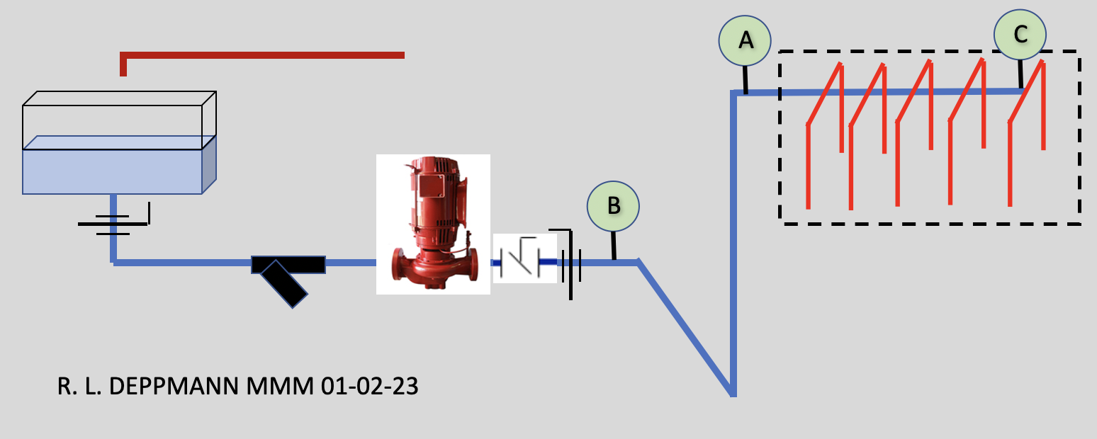
If the system flow rate and pressure requirement is constant, a drive may not make economic sense. In part one of this series we used a real-life example of a system, and the decision was to use a variable speed drive on the pump. The system had multiple on-off valves and the flow rate varied from 150 GPM design all the way down to 15 GPM at times. The pressure requirement was constant.
- We are trying to maintain pressure going into the process system. There are four standard choices of pressure control in this application. Three of them involve the pressure sensor location.
- POINT A: The sketch below shows position “A” as the choice we started with. The customer asked for a given pressure at the piping entrance to the system. That is point “A.” The plant manager asked for 50 PSIG at point A. If we set the pressure at 50 PSIG at point A, the pump will vary the speed to that set point. Ignoring the small elevation change in the storage tank level, this location will eliminate the variable pressure drop in the supply piping and the safety factor. The pump minimum head (control head) would be the 50 PSIG (115 feet) + 25 feet elevation or 140 feet. The curve will look like this.
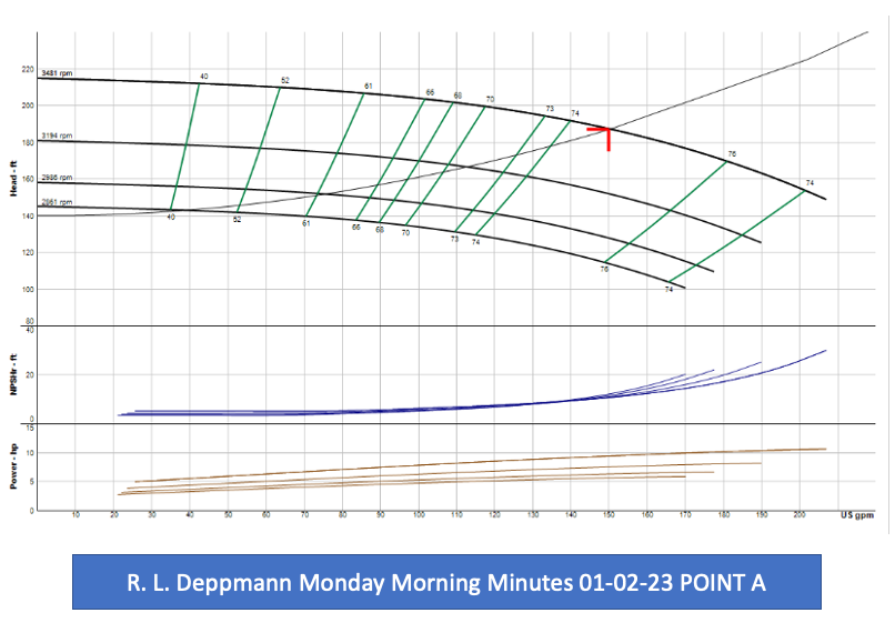 The speed will vary from 3481 RPM to 2850 RPM.
- POINT B: The point “B” location is the discharge of the pump. This would make sense economically since the sensor is right at the drive. It avoids going into the plant and disturbing the plant piping. It will save less energy because it will not eliminate the friction loss changes. The friction loss is after the sensor. It will cut off the over heading as the pump backs up on the curve. The pump minimum head (control head) would be the 50 PSIG (115 feet) + 25 feet elevation + 32 feet expected pipe friction or 172 feet.
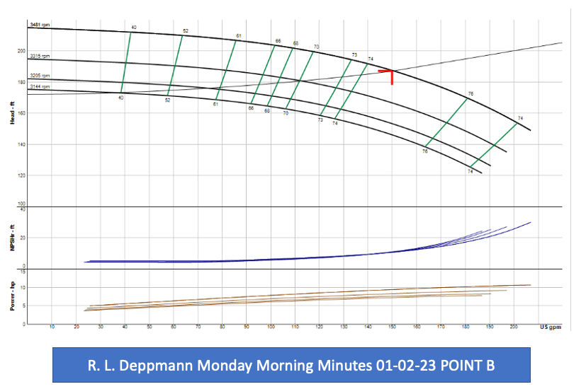
- The pump speed will vary from 3481 RPM to 3120 RPM
- POINT C: Point “C” is interesting. We discussed the system with the plant manager and found out that the machines only needed a minimum of 30 PSIG each. The 50 PSIG includes expected header piping losses in the plant. If we move to point C at the end of the header, we only need 30 PSIG. Any friction loss in the plant piping will show up as a reduction of pressure at point C and the pump will speed up. The pump minimum head will be 30 PSIG (70 feet) + 25 feet of elevation or 95 feet. The curve looks like this.
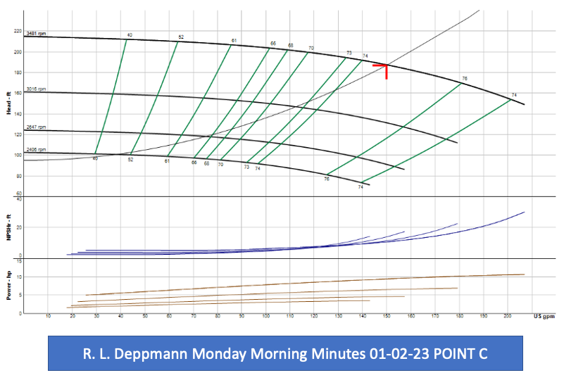
- The pump speed will vary from 3481 RPM to 2400 RPM
- If the pump is on a variable speed drive, the number of starts per hour is less of an issue. Check with the pump supplier but the number of starts per hour recommended by many motor manufacturers is 18 or 20 when operated on a drive.
Well, which point did the owner choose? The owner chose point B. It had the worst energy savings but the least cost. It also avoided a concern about breaking into the plant system. The risk was not worth the savings for the plant manager.
Once again, Happy New year to all the R. L. Deppmann Monday Morning Minutes readers.